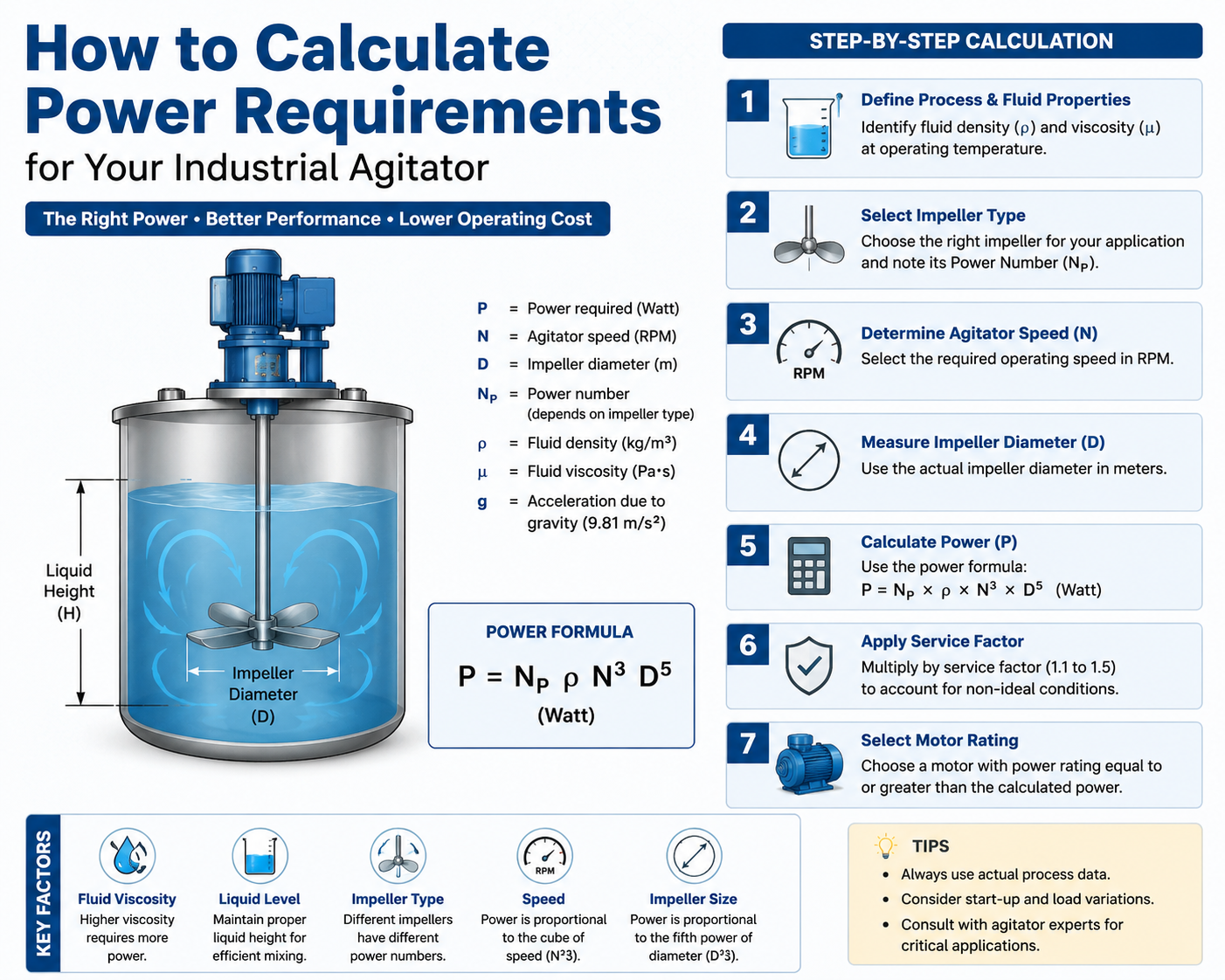
Choosing the wrong agitator motor size can be a costly mistake. An undersized motor may stall, overheat, or fail to provide the required mixing intensity, while an oversized motor increases equipment and energy costs. Agitators are widely used in chemical, pharmaceutical, food processing, water treatment, and mineral processing industries for blending liquids, suspending solids, improving heat transfer, and ensuring uniform reactions.
Modern fluid mixing technology depends on accurate power calculations to achieve efficient mixing, consistent product quality, and reliable equipment performance. Since every mixing duty requires a specific amount of mechanical power, correct agitator sizing is essential for process efficiency and energy savings.
This guide explains the standard method process engineers use to calculate agitator power requirements, based on industry references such as the Handbook of Industrial Mixing and standards from the American Society of Mechanical Engineers and the American Institute of Chemical Engineers.
Tip
What you will learn: the power equation, how to use the power number (Np), how viscosity and tank geometry change the answer, and a worked example you can adapt to your own process.
Before applying any formula, you need to gather the right inputs. Successful fluid mixing technology design depends on understanding how fluid properties, tank geometry, and impeller characteristics interact to influence power demand. Agitator power depends on five main groups of factors. If even one of these is overlooked, it often leads to incorrectly sized equipment.
Fluid Properties
Tank Geometry
Impeller Design
Operating Speed & Duty
Mechanical Losses
In turbulent flow, agitator power is usually calculated using the standard Power Number equation.
Power Equation
P = Np · ρ · N³ · D⁵
Notice the strong dependence on speed (cubed) and impeller diameter (to the fifth power). If the impeller diameter is doubled, the power requirement increases by 32 times. If the speed is doubled, the power increases by 8 times. This is why small changes in geometry or speed have such a large effect on power draw.
The power number is not a constant — it depends on the flow regime, which is described by the impeller Reynolds number:
Re = (ρ · N · D²) / μ
Three regimes are typically identified:
Note
Most industrial blending operations in water-like fluids operate in the turbulent regime, so the simple equation usually applies. Viscous polymer, oil, or coating applications often fall in the laminar or transitional range.
Follow this sequence every time. It mirrors the workflow that most mixer manufacturers use when sizing a unit for you.
Step 01
List the purpose for which the agitator should be employed: mixing of two miscible liquids, suspending a solid, drawing down a floating layer, heating or cooling, or dispersing gas into a liquid. The duty defines the right impeller, tank geometry and target impeller tip speed.
Step 02
Measure or look up the fluid density and viscosity at process temperature. Viscosity can fall by 80 per cent between cold start-up and hot operation, so always size for the worst case.
Step 03
A common starting point is D/T ≈ 0.3–0.4 for radial-flow turbines and 0.4–0.6 for axial-flow hydrofoils. A larger D/T ratio generally allows the system to run at lower speed and require less power to achieve the same blending time.
FMT (Fluid Mixing Technology) uses an engineering-based impeller selection methodology rather than relying only on standard D/T ratios.
Engineering Tip
The final impeller diameter is selected to achieve the required mixing performance with optimum power consumption and mechanical reliability.
The table below summarises FMT's standard impeller series, mapping each code to its impeller type, flow pattern, and typical application so you can narrow down a starting point before running the power calculation.
| Series | Code | Impeller Type | Flow Pattern | Typical Application |
|---|---|---|---|---|
| AF Series | AF-1 | Pitch Blade Turbine (PBT) | Mixed / Axial | Blending, heat transfer, solid suspension |
| AF Series | AF-2 | High Efficiency Hydrofoil | Axial | General blending, low power applications |
| AF Series | AF-3 | Advanced Hydrofoil | Axial | Large tanks, suspension, circulation |
| AF Series | AF-4 | Wide Blade Hydrofoil | Axial | High flow, low shear applications |
| AF Series | AF-5 | Gas-Liquid Hydrofoil | Axial + Radial | Gas dispersion, aeration, fermentation |
| AF Series | AF-6 | Marine Propeller | Axial | Low viscosity liquids, circulation duties |
| RF Series | RF-1 | Flat Blade Turbine (FBT) / Rushton Turbine | Radial | Gas dispersion, high shear mixing |
| RF Series | RF-2 | Curved Blade Turbine (CBT) / Smith Turbine | Radial | Gas-liquid dispersion, chemical reactions |
| RF Series | RF-3 | Cowl Turbine | Radial | Gas-liquid mass transfer applications |
| AN Series | AN-1 | Anchor | Tangential | Medium to high viscosity products |
| AN Series | AN-2 | Anchor with Scraper | Tangential | Heat transfer and wall cleaning |
| AN Series | AN-3 | Double Anchor | Tangential | Large diameter vessels |
| HR Series | HR-1 | Helical Ribbon | Axial | High viscosity mixing |
| HR Series | HR-2 | Double Helical Ribbon | Axial | Very high viscosity products |
| PD Series | PD-1 | Paddle | Mixed | Flocculation and gentle blending |
| PD Series | PD-2 | Gate Paddle | Mixed | Medium viscosity applications |
| DS Series | DS-1 | Saw Tooth Disperser | Radial | Dispersion and deagglomeration |
| DS Series | DS-2 | High Speed Disperser | Radial | Paints, coatings, adhesives |
| RS Series | RS-1 | Rotor-Stator Mixer | High Shear | Emulsification and homogenization |
| RS Series | RS-2 | Multi-Stage Rotor-Stator | High Shear | Fine emulsions and dispersions |
Continuing the sequence from Section 3 — setting the speed, sourcing the power number, and running the final checks.
Step 04
Use duty rules of thumb; for example, 5–6 m/s tip speed for solids suspension, 2–3 m/s for gentle blending to find N. Convert to revolutions per second before plugging into the power equation.
Step 05
Power numbers are published for standard impellers: Rushton turbine ≈ 5.0–6.0, pitched-blade turbine ≈ 1.3–1.5, HE-3 high-efficiency hydrofoil ≈ 0.3–0.4, marine propeller ≈ 0.4–0.5. Always cite the source chart you are using.
Step 06
Calculate P, then divide by gearbox and mechanical efficiency to get the installed motor power. Add a service factor (typically 1.10–1.25) for start-up transients, density upsets, and wear.
Step 07
Compare the calculated P to published correlations for your duty (for example, W per unit volume for blending). Large discrepancies usually mean an input was entered in the wrong unit or an impeller was chosen that is wrong for the duty.
Engineering Tip
FMT (Fluid Mixing Technology) uses an in-house Mixer Selection Tool to size each mixer case. The operating speed is selected based on multiple design checks such as tip speed, tank turnover rate, flow generated inside the tank, process duty, viscosity, impeller type, and D/T ratio. The speed is not selected only by thumb rule; it is optimised to achieve the required mixing performance with suitable power, torque, and mechanical reliability.
A water-treatment tank 3 m in diameter and 3.5 m liquid height, four standard wall baffles, fitted with a high-efficiency hydrofoil impeller. The duty is solids suspension at 4 m/s tip speed.
Re = (997 · 1.06 · 1.2²) / 0.00089 ≈ 1.7 × 10⁶ (fully turbulent)
P = 0.35 · 997 · (1.06)³ · (1.2)⁵ ≈ 1037.86 W ≈ 1.04 kW
Tip
Always round up, never down. A 1.1 kW motor on a calculated 1.31 kW load may trip overload protection during startup, struggle under peak mixing conditions, or overheat when fluid viscosity increases at lower temperatures. Selecting the next standard size provides a safety margin and improves reliability.
Result Summary
These errors show up in nearly every agitator failure we see. Treat them as a pre-flight checklist.
Answers to the most common engineering questions we receive when teams are working through agitator power calculations.
Calculating the power requirement of an industrial agitator is a tractable engineering problem once you treat it as a sequence: define the duty, gather fluid and tank data, choose the impeller, set the speed, look up the power number, and apply the equation with the right service factor and mechanical efficiency.
Get the number right, and you will specify a motor, gearbox, and seal combination that runs quietly, efficiently, and reliably for the full design life. This engineering approach forms the foundation of modern fluid mixing technology, helping manufacturers optimise performance, reduce operating costs, and improve process reliability. Get it wrong, and you will live with nuisance trips, premature wear, or a process that simply does not mix properly.
When in doubt, ask the mixer manufacturer for a sizing report and compare it to your own calculation. If the two numbers disagree by more than 15 per cent, the answer is usually in the assumptions: fluid viscosity, baffling, or duty not in the equation itself.