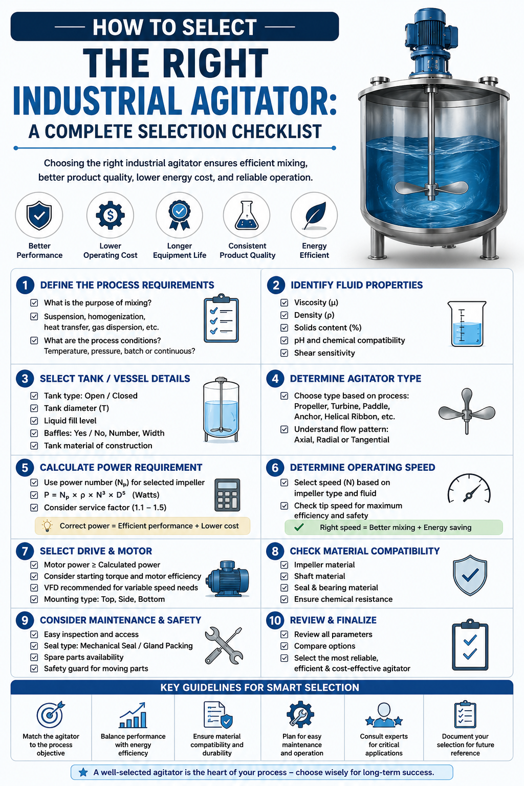
Choosing the wrong agitator can mean inconsistent blends, damaged equipment, wasted energy, and costly downtime. Industrial agitator selection is often complex due to the wide range of impellers, drives, and materials available.
This guide cuts through the complexity. Whether you are specifying equipment for a new plant or replacing an underperforming unit, the structured checklist below walks you through every critical factor so you can match the right agitator for your exact process requirements with confidence.
An industrial agitator is far more than a rotating blade inside a tank. It directly governs process outcomes, product quality, and operational cost. A poorly matched unit can cause:
A good initial selection helps save money, reduce maintenance, and maintain reliable process performance.
Tip
Advanced Fluid Mixing Technologies help optimize mixing efficiency, product consistency, and energy consumption across industrial processes.
Selecting the right agitator is a sequential process — each decision narrows the field for the next. Working through the eight steps below in order helps ensure that fluid characteristics, process objectives, and mechanical constraints are all accounted for before a final specification is issued.
The first step in selecting an agitator is understanding the characteristics of the fluid. Once you know the material's properties, it becomes much easier to choose the right mixing equipment.
Agitators are not interchangeable between tasks. The mixing duty dictates everything else in the selection process, and Fluid Mixing Technologies continue to evolve, offering more efficient solutions for a wide range of mixing applications.
Blending / Homogenisation
Bringing two or more miscible liquids to a uniform composition. Requires bulk flow rather than high shear.
Suspension
Keeping solid particles uniformly distributed. Governed by the just-suspended speed (Njs) and particle settling velocity.
Gas Dispersion
Breaking gas into fine bubbles for reaction or mass transfer. Demands high-shear, radial-flow impellers.
Emulsification
Dispersing immiscible liquids. High-shear rotor-stator or saw-tooth impellers are often needed.
Heat Transfer
Enhancing convective heat transfer to vessel walls or internal coils. Axial-flow impellers with close wall clearance work well.
Reaction
Providing contact between reagents. Mixing intensity depends on how fast the reaction happens and how easily mass transfer occurs.
The vessel itself shapes impeller choice and placement. Key parameters to document include:
The impeller is the main working part of the agitator. Modern Fluid Mixing Technologies have expanded the range of impeller designs available for specialised process requirements. The correct choice depends on your fluid viscosity and mixing objective.
| Impeller Type | Viscosity Range | Best For | Key Advantage |
|---|---|---|---|
| Hydrofoil (AF-Series) | Low–medium | Blending, suspension | High efficiency, low shear |
| Pitched-Blade Turbine | Low–medium | Suspension, blending | Good axial flow, versatile |
| Rushton Turbine (6-blade) | Low–medium | Gas dispersion, reaction | High shear, radial flow |
| Anchor | Medium–high | Heat transfer, blending | Close wall clearance |
| Helical Ribbon | High | Viscous blending | Full tank sweep |
| Gate / Paddle | Medium | Light blending | Simple, low-cost |
Source: Paul, E. L., Atiemo-Obeng, V. A., & Kresta, S. M. (Eds.). (2004). Handbook of Industrial Mixing: Science and Practice. Wiley-Interscience. (Adapted from standard impeller selection guidelines).
Once impeller type and size are established, the drive system must be sized correctly.
Sizing Tip
Power draw (P) is calculated using the Power Number (Np), which varies by impeller type, combined with fluid density and impeller speed. Always include a service factor of 1.15–1.25 when sizing the motor to account for process variability and startup loads.
The seal stops process fluid from leaking out along the agitator shaft. Selection depends on process pressure, temperature, and hygiene requirements.
Stuffing Box (Packed Gland)
Low-cost, tolerates low pressure; requires regular maintenance and repacking.
Single Mechanical Seal
Suitable for most standard process conditions; lower maintenance than packed glands.
Double Mechanical Seals
Used in hazardous, toxic, or high-pressure services and rely on a barrier fluid.
Magnetic Coupling (Mag Drive)
Completely sealless; ideal for highly hazardous materials where zero leakage is mandatory.
Material selection must account for corrosion, contamination risk, and operating conditions. The durability and efficiency of Fluid Mixing Technologies often depend on selecting the appropriate materials of construction.
Depending on your sector, your agitator may need to meet specific standards:
Note
Working through all eight steps before requesting a quote — rather than specifying an impeller or motor size alone — gives suppliers the full picture needed to propose equipment that is correctly matched to the process, not just to the tank.
Use this checklist as your quick-reference tool before finalising any agitator specification. Print it out or share it with your supplier.
| Selection Factor | Key Question to Ask | Checked |
|---|---|---|
| Fluid viscosity documented | What is the viscosity at operating temperature (cP)? | ☐ |
| Fluid density confirmed | What is the specific gravity of the process fluid? | ☐ |
| Newtonian / Non-Newtonian identified | Does viscosity change with shear rate? | ☐ |
| Operating temperature defined | What is the min / max process temperature range? | ☐ |
| Operating pressure defined | Is the vessel open, pressurised, or under vacuum? | ☐ |
| Corrosivity / hygiene class confirmed | Is food-grade, pharmaceutical, or chemical-resistant MOC needed? | ☐ |
| Mixing objective specified | Blending / suspension / gas dispersion / emulsification / heat transfer? | ☐ |
| Tank dimensions recorded | Diameter (T), working volume, H/T ratio confirmed? | ☐ |
| Baffle configuration noted | Standard four baffles or unbaffled / custom arrangement? | ☐ |
| Impeller type selected | Hydrofoil / Rushton / anchor / ribbon based on duty? | ☐ |
| Impeller diameter ratio set | D/T ratio confirmed (typically 0.25–0.45)? | ☐ |
| Off-bottom clearance specified | C/T ratio confirmed (typically 0.25–0.33)? | ☐ |
| Multiple impellers evaluated | H/T above 1.2 or multi-phase duty requires dual impellers? | ☐ |
| Drive configuration chosen | Top-entry / side-entry / bottom-entry? | ☐ |
| Motor power and service factor set | Np × density × N³ × D⁵ calculated with 1.15–1.25 service factor? | ☐ |
| Shaft sealing system selected | Packed gland / mechanical seal / double seal / mag drive? | ☐ |
| Materials of construction confirmed | 316L SS / Duplex / Hastelloy / lined for process fluid? | ☐ |
| Surface finish specified | Ra 0.8 µm (pharma) / Ra 1.6 µm (food) / standard (chemical)? | ☐ |
| Applicable standards confirmed | ATEX / EHEDG / 3-A / ASME / cGMP as required? | ☐ |
| Vendor documentation requested | Data sheet, FAT protocol, material certificates, O&M manual? | ☐ |
Source: Albright, L. F. (Ed.). (2008). Albright's Chemical Engineering Handbook. CRC Press. (Adapted from standard dynamic fluid agitation application parameters).
Engineering Tip
Work through this checklist top to bottom with your process engineer before contacting a supplier — a fully documented specification shortens quoting time and reduces the risk of receiving an incorrectly sized proposal.
Even experienced engineers occasionally fall into these traps. Being aware of them reduces costly rework.
| Mistake | Why It Happens | Risk Level | How to Avoid It |
|---|---|---|---|
| Scaling directly from lab to production | Assuming rpm translates directly between scales | High | Use dimensionless scale-up parameters such as Power per Unit Volume (P/V) or tip speed |
| Ignoring viscosity changes during the process | Sizing only for the starting or nominal condition | High | Design for the worst-case point in the process, not steady state — viscosity can shift by orders of magnitude in fermentation, polymerisation, or cooking duties |
| Underspecifying the seal | Basing seal choice only on steady-state conditions | Medium | Consider the full duty cycle, including startup, cleaning, and CIP/SIP if applicable |
| Omitting a structural assessment | Focusing on hydraulics while overlooking mechanical dynamics | Medium | Assess shaft and support structure for natural frequency to avoid resonance-driven fatigue failure |
| Overlooking maintenance access | Prioritising process performance over serviceability | Low–Medium | Confirm the seal and impeller can be accessed without a full vessel strip-down |
A reputable agitator supplier should be able to provide the following before you commit to a purchase. Experienced providers of Fluid Mixing Technologies can offer valuable guidance during equipment selection and system design.
| What to Request | Why It Matters |
|---|---|
| A detailed mixing calculation or CFD simulation | Justifies the impeller size and speed for your specific fluid and tank geometry, rather than a generic catalogue match |
| Reference installations in similar process conditions | Demonstrates proven performance in comparable viscosity, scale, and duty |
| Clear material traceability certificates | EN 10204 3.1 or 3.2 as required, confirming materials meet the specified grade |
| A Factory Acceptance Test (FAT) protocol | Verifies performance before the unit ships and reduces commissioning risk |
| Estimated power draw at the specified operating conditions | Confirms the motor and drive train are correctly sized for your actual duty |
| Recommended spare parts list and service intervals | Supports maintenance planning and reduces unplanned downtime |
Answers to the most common engineering questions we receive when teams are working through industrial agitator selection.
Selecting the right industrial agitator is a disciplined engineering process, not a catalogue exercise. By systematically working through fluid properties, mixing objectives, tank geometry, impeller type, drive configuration, sealing, materials, and compliance requirements — and using the checklist above at every stage — you give your process the best possible foundation for consistent, efficient, and safe operation.
If you are specifying a new agitator or reviewing an existing installation, use the checklist as your starting point. Engage your supplier with precise process data and ask for documented calculations. The investment in proper selection pays back many times over in reduced downtime, lower energy consumption, and reliable product quality.
Leveraging advanced Fluid Mixing Technologies further enhances process performance and long-term operational efficiency.