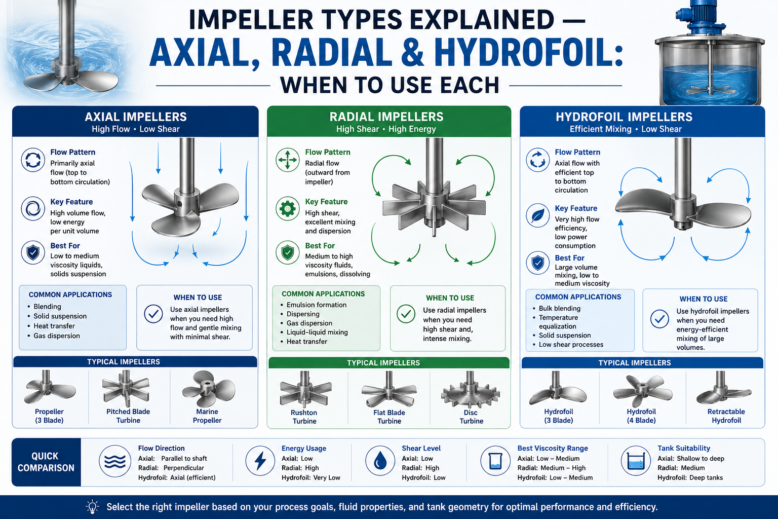
Choosing the wrong impeller for your mixing application can result in poor blending, wasted energy, product inconsistency, or even equipment damage. Whether you are working in chemical processing, pharmaceuticals, food production, or wastewater treatment, understanding the difference between axial flow, radial flow, and hydrofoil impellers is essential for process efficiency.
Modern fluid mixing technology relies heavily on proper impeller selection to achieve optimal flow patterns, energy efficiency, and product consistency.
This guide breaks down each impeller type, how it works, where it performs best, and how to choose the right one for your specific needs.
Tip
Advanced Fluid Mixing Technologies help optimize mixing efficiency, product consistency, and energy consumption across industrial processes.
An impeller is the rotating component inside a mixing vessel that generates fluid motion. It is usually attached to an agitator shaft and powered by a motor. The fluid flow pattern is influenced by the impeller blade shape, number, and the angle of attack of the blades, which has an impact on power consumption, mixing quality, shear rate, and particle size distribution.
As a core component of industrial fluid mixing technology, the impeller largely determines how effectively a process achieves its mixing objectives. Choosing the right impeller depends on several process factors:
There is no universal "best" impeller. Each type is engineered for a specific flow regime and application. Let us look at the three most widely used categories — different fluid mixing technology applications require different impeller designs to balance flow, shear, and energy consumption.
Axial flow impellers push fluid in a direction parallel to the impeller shaft — either downward (pumping-down) or upward (pumping-up). This creates a strong circulation flow throughout the tank, making it ideal for applications that require thorough mixing of the entire liquid volume.
The angled blades of an axial impeller work like a propeller or fan, pushing fluid through the tank. As the impeller rotates, it moves the fluid along the shaft, creating a circular flow pattern throughout the tank. In baffled tanks, this helps create effective mixing throughout the entire vessel. The result is efficient bulk blending with relatively low power input.
Pitched Blade Turbine (PBT)
Features blades angled at 30°–45° that create both axial and radial fluid flow. Versatile and commonly used.
Marine Propeller
A three- or four-blade impeller similar to a ship's propeller. Best suited for low-viscosity liquids and large-volume mixing applications.
Hydrofoil Impeller
A specialised axial impeller with aerofoil-shaped blades (covered in detail below).
Axial flow impellers are best suited for the following applications:
Typical Industries
Water and wastewater treatment, food and beverage mixing, pharmaceutical blending, and general-purpose liquid mixing.
Radial flow impellers push fluid outward from the blade tips at a right angle to the shaft. The fluid rushes to the tank sidewall and then travels both up and down. The geometry produces significantly higher shear forces than axial designs.
As the impeller spins, centrifugal force accelerates fluid outward at high velocity. This radial discharge creates intense turbulence near the impeller blades, making radial impellers excellent for operations that require breaking up droplets, dispersing gases into liquids, or mixing high-viscosity fluids that resist axial pumping.
Rushton Turbine (Flat Blade Disc Turbine)
The most widely used radial flow impeller. Six flat blades mounted on a central disc, widely used for gas dispersion in bioreactors and chemical reactors.
Flat Blade Paddle
Simple flat blades providing moderate radial flow. Suited for gentle mixing at low speeds.
Curved Blade Turbine
Concave blades that reduce power fluctuation during gas dispersion, an improvement over the standard Rushton.
Sawtooth / Cowles Disc
High-speed radial impeller for dispersion and emulsification. Generates very high shear forces near the blade tips.
Radial impellers are the right choice when:
Common Applications
Fermentation, paint and coating manufacturing, polymer processing, pharmaceutical ingredient dispersion, and chemical production.
Hydrofoil impellers are an advanced version of axial flow impellers. Instead of flat or simply pitched blades, hydrofoil impellers feature curved, aerofoil-profiled blades that are engineered to minimise drag and flow separation while maximising pumping efficiency.
The blade design of a hydrofoil impeller is inspired by the aerodynamic shapes used in aircraft wings. The cross-section is shaped like an airfoil — thin, curved, and optimised for laminar attachment of fluid flow. This design significantly reduces turbulent wake behind the blade, increasing pumping capacity per unit of power consumed. Hydrofoil impellers produce strong downward fluid flow while consuming less energy than traditional pitched blade turbines.
Hydrofoil impellers are the ideal choice when:
Note
Industries that commonly use hydrofoil impellers include biotechnology, aerobic fermentation, wastewater aeration, and large-scale food processing.
| Feature | Axial Flow | Radial Flow | Hydrofoil |
|---|---|---|---|
| Flow Direction | Axial (parallel to shaft) | Radial (perpendicular to shaft) | Axial/mixed |
| Best For | Low-viscosity blending, heat transfer | High-viscosity, dispersion, emulsification | Gas-liquid mixing, fermentation |
| Shear Level | Low to medium | Medium to high | Low |
| Power Draw | Low | High | Low to medium |
| Common Industries | Water/wastewater, pharma, food | Chemicals, coatings, polymers | Biotech, fermentation, aeration |
| Typical Speed | High RPM | Medium to high RPM | Medium RPM |
No single impeller is best for every process. The right selection depends on a combination of fluid properties, process objectives, and operating conditions. Here is a practical decision framework.
Tank aspect ratio (height-to-diameter ratio) significantly affects impeller choice. Tall, narrow tanks benefit from axial or hydrofoil impellers that drive strong vertical circulation. Wide, shallow tanks often perform better with radial impellers that create outward circulation hitting the walls. When mixing multiple phases (liquid-liquid, gas-liquid, solid-liquid), using dual or multiple impellers on one shaft is common practice.
Hydrofoil impellers typically offer the lowest energy consumption per unit of mixing achieved in low-viscosity applications. Radial impellers consume more power per volume due to their high-shear discharge pattern. Factor in not just the motor rating but also long-term operational electricity costs, especially for continuous mixing processes.
Even experienced engineers make these errors. Avoid them to protect both process performance and equipment lifespan.
| Mistake | Consequence |
|---|---|
| Using a radial impeller where axial is needed | Leads to poor top-to-bottom mixing, stratification, and dead zones near the bottom of the tank |
| Oversizing the impeller | An impeller that is too large relative to tank diameter causes excessive wall shear, vortexing, and wasted energy |
| Ignoring baffles | Without baffles, both axial and radial impellers cause solid-body rotation and poor mixing. Four standard baffles (10% of tank diameter) are the norm |
| Selecting based on cost alone | A cheaper, ill-suited impeller costs more in energy, downtime, and product quality failures over time |
| Neglecting shaft critical speed | High-speed radial impellers can cause shaft vibration and bearing failure if the rotational speed approaches the shaft's natural frequency |
Pharmaceutical and Biotech
Hydrofoil and low-shear axial impellers are the standard for cell culture, fermentation, and API blending. The Rushton turbine remains dominant in sparged bioreactors where oxygen transfer must be maximised without excessive cell damage.
Chemical and Petrochemical
Radial impellers such as the flat blade turbine and Rushton are widely used for high-viscosity chemical reactions, polymerisation, and liquid-liquid extraction. Axial impellers serve bulk blending and heat-exchanger-integrated tanks.
Food and Beverage
Sanitary-grade axial and hydrofoil impellers are preferred for dairy, brewing, juice, and sauce production. CIP (clean-in-place) compatibility and surface finish standards (Ra values) are critical selection criteria beyond the impeller type itself.
Wastewater Treatment
Large-diameter hydrofoil impellers are widely used in aeration basins for their ability to create high oxygen transfer rates at very low energy costs. Axial flow impellers with solid-suspension duty are used in sludge holding tanks and equalisation basins.
Matching impeller type to fluid properties, mixing objective, and tank geometry is the single most effective way to avoid the common mistakes above — and it is worth confirming the choice with your supplier's mixing calculations before committing to a final specification.
Answers to the most common engineering questions we receive about impeller selection for industrial mixing applications.
Understanding impeller types is not just a theoretical exercise — it directly impacts product quality, energy costs, and equipment reliability. To summarise:
These impeller designs form the foundation of modern fluid mixing technology across chemical, pharmaceutical, food, and wastewater processing industries.
When in doubt, consult with a mixing equipment specialist or conduct a small-scale trial with representative fluid. The right impeller selection from the start saves high cost and rework down the line.