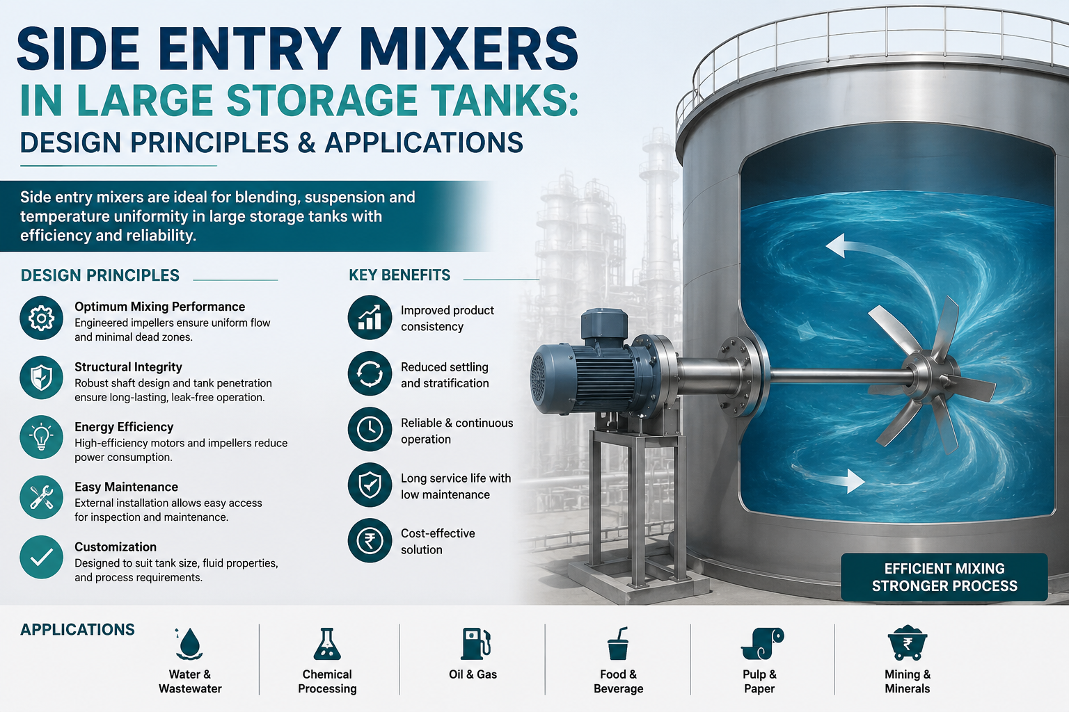
When managing large storage tanks, whether in a petroleum refinery, a chemical plant, or a water treatment facility, ensuring uniform fluid composition is a persistent engineering challenge. Stratification, sedimentation, and heat gradients silently reduce process efficiency, increase product inconsistency, and accelerate equipment degradation.
Side entry mixers have become the industry's preferred solution for large-volume tank agitation. Unlike top-mounted agitators, they allow continuous mixing without opening the tank roof, making them safer, more energy-efficient, and easier to maintain even on sealed or pressurised vessels. This guide covers everything you need to know: how they work, what governs their design, and where they deliver the most value.
Fluid Mixing Technologies specialises in engineered mixing solutions for large storage tanks, helping industries achieve efficient fluid circulation, product consistency, and long-term operational reliability.
A side entry mixer (also called a side entry agitator) is a mixing device installed through the sidewall of a storage tank, with its impeller positioned below the liquid surface. The motor and gearbox sit outside the tank, driving a shaft that penetrates the tank wall via a mechanical or packed seal.
This configuration differs fundamentally from top entry agitators, which are mounted on nozzles or beams at the roof. Side entry units are optimised for bulk fluid motion, creating a sweeping, circulatory flow pattern rather than localised intense agitation. They work best in tanks larger than 500 m³, where top entry designs would require impractically large shafts or multiple units.
Key Distinction
Side entry mixers prioritise bulk fluid circulation and low energy consumption over high-shear mixing. They are designed to move large fluid volumes efficiently, not to perform emulsification or dispersion tasks that require intense local turbulence.
Large storage tanks are rarely well-mixed by default. Several natural phenomena work against homogeneity — each one quietly working against product quality and tank efficiency until it is actively counteracted.
Phenomenon 01
Temperature differences between incoming and stored fluids create density layers that resist natural mixing, leaving the tank divided into thermal bands rather than a single uniform body of fluid.
Phenomenon 02
Heavy particles, wax crystals, or solids settle to the tank floor over time, reducing effective volume and causing blockages in outlet lines and pipework.
Phenomenon 03
In blending applications, differing fluid densities create stable layers that can persist for weeks without agitation, undermining consistency across the batch.
Phenomenon 04
In petroleum tanks, lighter hydrocarbons rise to the surface, creating vapour pockets and measurement inaccuracies that distort inventory readings.
Left unaddressed, these issues translate directly into product quality failures, measurement errors, increased pipeline blockages, and costly tank cleaning operations. Active agitation with a properly designed side entry mixer resolves all of these.
With extensive expertise in industrial mixing applications, Fluid Mixing Technologies designs side entry mixer systems tailored to prevent stratification, sedimentation, and product quality issues.
Designing a side entry mixer for a large storage tank is not simply a matter of selecting a motor and attaching a propeller. Several interdependent parameters must be evaluated together to achieve optimal performance.
The impeller is the heart of the side entry mixer. For large-tank applications, the dominant choices are:
| Impeller Type | Characteristics | Best Application |
|---|---|---|
| Marine Propeller (3-blade) | High axial flow, low shear, efficient at low RPM | Petroleum blending, crude oil homogenisation |
| Hydrofoil Impeller | Optimised lift-to-drag ratio, minimal turbulence losses | Low-viscosity blending, fuel oils, water treatment |
| Pitched Blade Turbine | Combined axial and radial flow, more aggressive mixing | Medium-viscosity fluids, chemical tanks |
| High-Efficiency Axial Flow | Maximum circulation per unit power, low noise | Large petroleum storage, water reservoirs |
Source: Compiled data from fluid mixing and large-tank blending selection frameworks: ScienceDirect Fluid Dynamics, Wiley Industrial Mixing Guides, and foundational fluid dynamics indices on ResearchGate Impeller Performance Profiles.
For most large petroleum storage tank applications, three-blade marine propellers and high-efficiency axial flow impellers are the standard choice. They deliver maximum bulk flow at minimum power consumption, critical when mixers run continuously for months.
Fluid Mixing Technologies applies advanced engineering principles to optimise impeller selection, mixer positioning, and power efficiency for diverse storage tank applications.
The horizontal and vertical position of the mixer, as well as its angular orientation relative to the tank centreline, profoundly affect the mixing efficiency. Key guidelines include:
Guideline 01
Most side entry mixers are installed at 7–15° off-centre from the tank diameter, creating a swirling, circulatory flow around the tank perimeter rather than a direct jet that hits the opposite wall.
Guideline 02
A slight downward tilt of 2–5° directs the axial jet toward the tank floor, preventing sedimentation in the bottom cone area.
Guideline 03
The mixer centreline is typically positioned at 20–30% of the maximum liquid level above the tank floor, keeping the propeller submerged at minimum operating level and drawing fluid from lower stagnant zones.
Guideline 04
Large tanks (>10,000 m³) often require two or more mixers positioned 180° apart to achieve complete circulation coverage without dead zones.
Side entry mixers are driven by an electric motor connected to the impeller shaft through a right-angle or inline gearbox. The gearbox reduces the high rotational speed of the motor to the optimal propeller speed, which for large tank applications is typically 30–150 RPM.
Power sizing is determined by the required fluid turnover rate — the number of times the full tank volume should be circulated per hour. For petroleum storage tanks, a turnover rate of 1–4 times per hour is generally adequate. The required shaft power can be estimated using the following relationship:
Variable Frequency Drives (VFDs) are frequently specified on modern side entry mixer installations. They allow the mixing intensity to be adjusted based on operational needs, reduce starting current, and enable precise speed control — extending the service life of mechanical components significantly.
Because the shaft penetrates the tank wall below the liquid level, a reliable seal is critical. The choice of seal depends on the fluid type, operating pressure, and whether the tank handles volatile or hazardous materials.
Seal Type 01
The traditional approach for non-hazardous fluids at ambient pressure. Low cost, easy maintenance, but requires periodic re-packing.
Seal Type 02
Suitable for clean, low-viscosity fluids. Provides a more consistent leak-free performance than packed gland seals.
Seal Type 03
Required for hazardous, toxic, or volatile fluids. A buffer fluid between the two seal faces prevents process fluid from escaping to atmosphere.
Seal Type 04
The highest-performance option for pressurised or highly toxic applications, using inert gas (typically nitrogen) as the sealing medium.
Seal selection must align with both the fluid characteristics and the applicable environmental regulations. In petroleum storage terminals, double or tandem mechanical seals are increasingly mandated to minimise hydrocarbon emissions.
The shaft of a side entry mixer spans from the drive assembly outside the tank to the impeller submerged in the fluid. This configuration generates significant bending moments and thrust loads. Critical design considerations include:
Consideration 01
Must resist both torsional and bending stresses. Carbon steel is standard; stainless steel (316L) or duplex grades are specified for corrosive services.
Consideration 02
Many designs include a bearing mounted inside the tank near the impeller to reduce shaft deflection and vibration. These bearings must be compatible with the process fluid, as external lubrication is impractical.
Consideration 03
The shaft's natural frequency must be separated from the operating speed range by a minimum margin (typically 20–25%) to prevent resonance-induced fatigue failure.
Sizing and evaluating a side entry mixer comes down to three interlinked parameters: how fast the fluid actually moves, how much force drives that motion, and what flow regime results.
The primary measure of mixing adequacy in a storage tank is not turbulence intensity; it is the bulk fluid velocity and the resulting turnover time. For most storage tank applications, a minimum bulk velocity of 0.05–0.15 m/s at the tank wall is sufficient to prevent stratification and sedimentation. The required flow rate can be calculated as:
Side entry mixers deliver mixing by generating a directed momentum flux and a thrust force that drives bulk circulation. The delivered thrust (in Newtons) is the critical sizing parameter, not power alone. A high-efficiency impeller delivering the same thrust as a lower-efficiency design may require 20–30% less power, directly reducing operating costs.
Thrust is also the parameter used to size the mixer mounting flange, nozzle reinforcement, and tank wall structural requirements. For large tanks with thin shell walls, a detailed finite element analysis of the nozzle stress is often required.
The Reynolds number (Re) determines whether the flow generated by the mixer is laminar, transitional, or turbulent:
Re > 10,000
Efficient bulk mixing. This is the target for low-to-medium viscosity applications (<500 cP).
Re 100–10,000
Mixing efficiency drops. Power consumption increases relative to the flow generated.
Re < 100
Applicable only to high-viscosity fluids. Side entry mixers are generally not recommended above 1,000 cP; top entry agitators with anchor or helical ribbon impellers are more appropriate.
Side entry mixers serve a broad range of industries wherever large-volume fluid homogeneity is critical. Below are the principal application sectors.
This is the largest and most demanding application domain for side entry mixers. In crude oil and refined products terminals, mixers perform several essential functions:
Side entry mixers in petroleum service are typically specified to API 2000 and API 650 standards, with particular attention to the seal system to meet API 682 mechanical seal specifications.
Chemical storage tanks present a diverse range of mixing challenges depending on the product. Common applications include:
Chemical service mixers typically require stainless steel (316L, 904L) or alloy wetted parts, and double mechanical seals to prevent fugitive emissions in compliance with REACH and local environmental regulations.
In water treatment, side entry mixers serve large equalisation basins, buffer tanks, and sludge holding tanks. Their key roles include:
Biogas mixing in anaerobic digestion tanks is a specialised application where submersible side-entry mixers maintain the sludge in suspension for optimal methane production.
While top entry agitators dominate hygienic processing environments, side entry mixers are used in large-volume storage and blending tanks for:
Food-grade applications require FDA/EC-compliant elastomers, hygienic mechanical seals, and surface finishes appropriate to CIP (Clean-in-Place) procedures.
While side entry mixers dominate large-volume storage applications, the choice between configurations should be based on a structured evaluation of the process requirements.
| Criterion | Side Entry Mixer | Top Entry Mixer |
|---|---|---|
| Tank Volume Suitability | >500 m³ (optimal >2,000 m³) | 50–2,000 m³ (standard) |
| Installation Disruption | Minimal — no roof penetration needed | Requires roof nozzle and support structure |
| Hot-Work on Existing Tanks | Easier — shell penetration, lower risk | Complex — roof welding on live tank |
| Mixing Intensity | Moderate (bulk circulation) | High (local and bulk) |
| High-Viscosity Fluids (>1,000 cP) | Limited suitability | Preferred (with anchor/ribbon impeller) |
| Energy Efficiency (Large Tanks) | High — lower specific energy per m³ | Lower for equivalent volume coverage |
| Maintenance Access | Good — external motor/gearbox | Good — accessible from roof |
| Floating Roof Tanks | Fully compatible | Not compatible |
Source: Compiled from industrial mixer selection literature and manufacturer technical resources, including Dynamix Agitators, Mechanimix, Milton Roy Mixing, and DisperseTech side-entry and top-entry mixer guides.
Even a correctly specified side entry mixer can underperform if these recurring failure modes aren't designed against from the outset.
Even with a correctly specified mixer, dead zones can persist near the centre of the tank floor, particularly in flat-bottom tanks. Solutions include:
The shaft seal is the most maintenance-intensive component in a side entry mixer installation. Premature failure is usually caused by:
Excessive vibration is a sign that the shaft is operating at or near its critical speed, or that the impeller has suffered damage (bent blade, erosion, corrosion). Mitigation measures include:
Even a well-designed side entry mixer will underperform if installed incorrectly. The following steps are essential:
Answers to the most common engineering questions we receive when teams are specifying side entry mixers for large storage tanks.
Side entry mixers represent one of the most effective and economically sound solutions for maintaining fluid homogeneity in large storage tanks. When designed correctly with the right impeller geometry, installation angle, seal system, and drive configuration, they operate reliably for years with minimal intervention, protecting product quality and reducing operational risk.
The design process demands an integrated view of fluid dynamics, mechanical engineering, and process requirements. Shortcutting any element — impeller sizing, seal selection, or shaft rotordynamics — creates problems that are costly to correct after installation. Early, thorough engineering investment is always the most economic path.
To discuss how a side entry mixer can be engineered for your specific storage tank application, contact the Fluid Mixing Technologies team at fluidmixtech.com. Our engineers are ready to help you specify the right solution from day one.