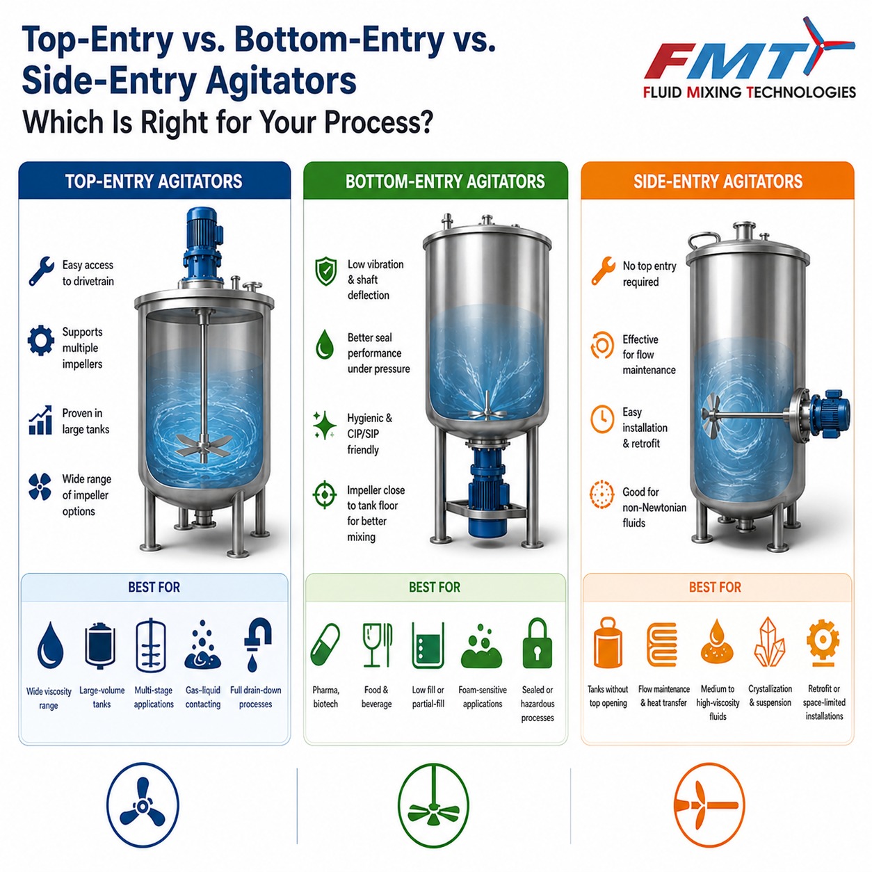
Whether you're mixing a polymeric resin, blending a pharmaceutical suspension, or homogenizing a fermentation broth, choosing how your agitator enters the tank is one of the most consequential decisions you'll make. Pick the wrong configuration, and you'll face seal failures, poor mixing efficiency, product contamination, or a maintenance problem that never goes away. This guide cuts through the noise. You'll get a clear explanation of how each configuration works, where each excels and where it falls short, and the concrete factors that should drive your decision.
A mechanical device installed in a process vessel to induce fluid motion — promoting mixing, heat transfer, mass transfer, or suspension of solids. It consists of a motor, a drive assembly, a shaft, and one or more impellers.
The entry point of the shaft (top, bottom, or side) is not a cosmetic detail. It directly shapes seal complexity, flow patterns, structural loads, and long-term operating cost.
Both configurations are refined over decades and backed by mature engineering literature. Neither is universally better — context is everything.
Top-entry
Most common in CPI
Bottom-entry
Sealed, hygienic
Side-entry
Large storage tanks
Mounts on or above the vessel's top head, with the shaft extending downward into the tank. The motor, gearbox, and seal assembly sit above the tank — accessible without draining the vessel.
Design characteristics
Best-fit applications
Impeller types — select to explore
Rushton turbine
Radial-flow impeller ideal for gas dispersion in fermenters and bioreactors.
Smith turbine
Variant of Rushton with concave blades; improved gas-handling capacity.
Pitched-blade turbine (PBT)
Axial-flow impeller for bulk blending and solids suspension.
Hydrofoil (AF-2 / AF-3 / AF-4 / AF-5)
High efficiency, low shear — ideal for shear-sensitive fluids.
Anchor impeller
High-viscosity applications requiring wall proximity and scraping action.
Helical ribbon
Continuous wall-scraping for very high-viscosity and non-Newtonian fluids.
Cowles disc
High-shear disperser for solid dispersion in the paint and coatings industry.
Advantages vs. limitations
Advantages
Limitations
Fluid Mixing Technologies offers engineered top-entry mixing solutions designed to improve blending efficiency and support reliable operation across industrial processing applications.
Learn more →Mounts beneath the vessel's lower head, with the shaft entering upward through a centrally located bottom nozzle. The impeller sits very close to the vessel floor — exactly where mixing is often most critical and most difficult to achieve with a top-mounted shaft.
Because the shaft is short and supported close to both ends, bottom-entry systems inherently have far lower shaft deflection and vibration than long top-entry shafts.
Bottom-entry configurations have carved out a strong position in industries where hygiene, precision, and containment are paramount.
Advantages vs. limitations
Advantages
Limitations
Fluid Mixing Technologies designs bottom-entry agitators to hygienic standards, delivering precision mixing for pharmaceutical, biotech, and food & beverage applications.
Explore solutions →Mounts through a nozzle on the vessel sidewall, with the shaft entering horizontally (or at a slight downward angle). The motor and gearbox are mounted externally at the side, and the impeller creates a sweeping horizontal circulation pattern that promotes bulk fluid movement.
The shaft in a side-entry configuration is very short and operates close to both bearing supports, resulting in an inherently rigid, low-vibration arrangement.
Multiple side-entry agitators are often installed on a single large tank, arranged at offset angles to create a rotational circulation pattern that sweeps the entire tank volume.
Common impeller types — side-entry service
Marine propeller — 3-blade
Optimised for high-flow, low-shear bulk circulation in low-viscosity liquids.
Marine propeller — 4-blade
Higher thrust variant for larger tank volumes and denser fluid applications.
Pitched-blade turbine (PBT)
Suitable for moderate-viscosity blending and gentle slurry circulation in side-entry service.
Axial-flow impeller
Used where directional bulk circulation and stratification prevention are the primary objectives.
Advantages vs. limitations
Advantages
Limitations
Fluid Mixing Technologies engineers side-entry agitators for large-volume storage and process tanks, delivering reliable bulk circulation and stratification control across oil & gas, water treatment, and biogas applications.
Explore solutions →Side-entry configurations are the preferred choice wherever tank size, economics, or operational flexibility make top- or bottom-entry designs impractical.
Advantages vs. limitations
Advantages
Limitations
Fluid Mixing Technologies engineers side-entry agitators for large-volume storage and process tanks, delivering reliable bulk circulation and stratification control across oil & gas, water treatment, and biogas applications.
Explore solutions →When choosing between top-entry, bottom-entry, and side-entry configurations, the following factors should be evaluated systematically. There is no single right answer — but there is usually a clearly better answer once you have mapped these factors against your process requirements.
| Selection factor | Top-entry | Bottom-entry | Side-entry |
|---|---|---|---|
| Shaft length & stability | Moderate risk Long shaft; vibration risk in large tanks; may need intermediate bearing |
Best Short, rigid shaft; minimal vibration; no intermediate bearing needed |
Best Very short shaft; highly rigid; low bending stress and minimal vibration |
| Seal type & complexity | Simpler Single mechanical seal or packing; lower pressure differential at seal face |
Complex Double mechanical seal with barrier fluid; operates under full liquid head |
Moderate Single or double mechanical seal; sidewall-mounted with shut-off isolation device |
| Maintenance access | Easy Motor and gearbox above grade; easy visual inspection and replacement |
Challenging Drive below tank; requires underfloor access or elevated tank structure |
Easy Excellent side-access; maintenance possible without tank entry in many cases |
| Impeller-to-bottom clearance | Limited Impeller placement limited by shaft length; potential dead zone near floor |
Optimal Impeller naturally sits close to vessel bottom; eliminates dead zone |
Moderate Mounted at lower sidewall elevation; less effective for complete bottom sweeping |
| Hygienic design | Adequate Adequate for most industrial use; harder to achieve full 3-A compliance |
Preferred Preferred for sanitary processes; supports full drainability and CIP |
Not preferred Generally not preferred for hygienic / sanitary applications |
| Low-level mixing | Limited Impeller may be uncovered during low-fill operation |
Excellent Effective at very low fill levels; impeller always submerged |
Limited Performance drops significantly at low liquid levels; requires minimum submergence |
| Viscosity range | Widest Excellent — handles low to extremely high viscosity with the right impeller |
Moderate Best for low-to-medium viscosity; high viscosity limits impeller selection |
Narrowest Best for low-viscosity, high-volume applications; limited for high-viscosity fluids |
| Foam sensitivity | Risk Top impeller can entrain air and worsen foam generation |
Best Submerged impeller avoids surface disturbance; reduces foam risk |
Good Designed for gentle bulk circulation; lower air entrainment vs. top entry |
| Containment (hazardous media) | Good Good with proper seal; mag-drive top-entry available but rare |
Excellent Excellent with mag-drive or double mechanical seal with sterile barrier |
Good Good for large hydrocarbon tanks; commonly used with API sealing arrangements |
| Capital cost | Lower Generally lower for standard industrial sizes |
Higher Higher due to seal system complexity and tank elevation requirements |
Economical Economical for very large storage tanks due to reduced shaft length |
| Tank size range | Large Scales well to very large vessels (>100,000 L) |
Small–Medium Most common in small-to-medium vessels (<30,000 L) |
Very large Ideal for very large storage tanks and terminals (>500 KL to several thousand KL) |
Not sure which configuration fits your process? Fluid Mixing Technologies provides application engineering support to help you select the right agitator configuration for your specific process, vessel, and operating conditions.
Talk to an engineer →Choosing between top-entry, bottom-entry, and side-entry configurations is a decision process, not a coin flip. Work through the following steps in order — they will converge on the right answer for most processes.
Define your process fluid profile Fluid characterisation
Before anything else, characterise your fluid. Viscosity is the dominant variable. If your process fluid exceeds roughly 50,000 cP (thick resins, polymer melts, or adhesives), top entry wins by default — bottom entry cannot practically deliver the large-diameter, low-speed impellers that high-viscosity fluids demand. For very large volumes at low viscosity requiring bulk circulation, side entry is the economic choice. For thin, water-like fluids in process vessels, both top and bottom entry are viable.
Evaluate hygiene and containment requirements Regulatory fit
Are you working in a regulated environment? Pharma, biotech, food and beverage, and cosmetics all carry specific sanitary and cleanability requirements. If your process requires 3-A compliance, full CIP drainability, or sterile seal integrity across the batch, bottom entry is your strong default. If your process involves a corrosive or mildly hazardous fluid with no exceptional hygiene requirements, a top-entry system with a single mechanical seal is simpler and cheaper. For large-volume hydrocarbon storage with containment needs, side entry with API sealing is the industry standard.
Assess tank geometry and size Vessel layout
For tall, narrow tanks (high H/D ratio), top-entry shafts become very long, creating deflection and critical-speed challenges — this tips the balance toward bottom entry. For wide, shallow tanks with large diameters, top entry is typically the natural fit. Very large vessels above 30,000 litres are overwhelmingly served by top-entry or side-entry designs, with side entry preferred for pure storage and circulation duties.
Consider maintenance philosophy and infrastructure Operations
Bottom-entry agitators require either an elevated tank or a pit below the vessel. If your facility layout does not accommodate this, or if below-grade access is restricted for safety reasons, top entry is the more practical choice — even if not theoretically optimal. Side-entry agitators, with their shut-off isolation devices, offer the greatest operational flexibility for in-service maintenance.
Evaluate the full life-cycle cost Economics
Do not let upfront capital cost be the deciding factor in isolation. Seals in bottom-entry systems are more complex, but shorter shafts and better vibration characteristics can mean lower bearing and coupling wear over time. Model both configurations over a 10-year horizon before concluding. Fluid Mixing Technologies emphasises long-term performance, operational efficiency, and reduced maintenance requirements across the equipment lifecycle.
Use this reference table to identify the recommended configuration based on your scenario. Filter by configuration to narrow down your options.
| Scenario | Recommended configuration |
|---|---|
| Viscosity > 50,000 cP (pastes, polymer melts, adhesives) | Top entry |
| Hygienic or CIP required (pharma, biotech, food, 3-A) | Bottom entry |
| Tank volume > 30,000 L — bulk or reaction vessel | Top entry |
| Tank volume > 500 KL — storage or circulation duty | Side entry |
| Foam or surface disturbance sensitive (fermentation, cell culture) | Bottom entry |
| Multiple impeller stages required (gas dispersion, tall vessels) | Top entry |
| Tall narrow tank with H/D ratio > 2 | Top entry — multi-stage axial flow coverage |
| Sterile or hermetic containment (toxic, volatile, biological) | Bottom entry — mag-drive preferred |
| General industrial blending (solvents, resins, intermediates) | Either — optimise on cost and process |
| Large storage tanks requiring bulk circulation | Side entry |
| Crude oil / edible oil / asphalt storage tanks | Side entry |
| Temperature homogenisation in heated tanks | Side entry |
| Tank farm stratification prevention | Side entry |
| Open-tank slurry circulation (FGD, wastewater, digesters) | Side entry / Top entry |
| Low-viscosity, high-volume blending | Side entry |
| High solids suspension in compact tanks | Top entry |
| Complete drainability required | Bottom entry |
| Reactor with heat-transfer jacket / limpet coil | Top entry |
| Digesters and biogas reactors (large volume) | Side entry |
| Existing storage tank retrofit with minimum modification | Side entry |
| Very large diameter tank with low liquid height | Side entry |
| High-shear dispersion or emulsification | Top entry |
| Sanitary batch processing with frequent cleaning | Bottom entry |
Still unsure which configuration fits your process? Fluid Mixing Technologies provides application engineering support to help you select the right agitator configuration for your specific process, vessel, and operating conditions.
Talk to an engineer →To make this more concrete, here is how the choice typically plays out across major process industries.
| Industry | Preferred Configuration | Primary Reason |
|---|---|---|
| Pharmaceuticals & Biotech | Bottom Entry | Hygienic sealing, sterility, CIP compliance |
| Food & Beverage | Bottom Entry | 3-A sanitary standards, full drainability |
| Specialty Chemicals | Top Entry | Wide viscosity range, large vessels |
| Polymers & Resins | Top Entry | High viscosity, anchor/ribbon impellers |
| Cosmetics & Personal Care | Situation-Dependent | Varies by product viscosity and batch size |
| Pulp & Paper | Top Entry | Large volumes, fibre suspension, high viscosity |
| Wastewater Treatment | Top Entry | Very large open tanks, cost sensitivity |
| Industrial Fermentation (Commodity) | Top Entry | Scale and cost efficiency |
| Industrial Fermentation (Biopharma) | Bottom Entry | Sterile containment and CIP requirements |
| Compressed Biogas (CBG) Plants | Side Entry | Aerobic and anaerobic digesters |
| Ethanol Distillery | Side Entry | Large fermenters, solids suspension, temperature uniformity, energy-efficient circulation |
| Flue-Gas Desulfurization (FGD) | Side Entry | Limestone/gypsum slurry circulation in very large tanks |
| Water Treatment — Condensate Polishing Unit | Side Entry | Resin/slurry circulation and prevention of settling |
| Edible Oil Blending | Side Entry | Gentle blending, temperature uniformity, large storage tank circulation |
| Crude Oil Storage | Side Entry | Prevents stratification, sludge deposition, maintains temperature uniformity |
| Asphalt / Bitumen Tanks | Side Entry | Maintains heat distribution and prevents settling in high-volume heated tanks |
| Mining & Mineral Slurry Storage | Top / Side Entry | Solids suspension and slurry homogenisation |
Even experienced engineers make these errors. Understanding them upfront can save significant cost and downtime over the life of the equipment.
Top-entry systems are often less expensive upfront, leading project teams to default to them without evaluating long-term seal replacement and maintenance costs. In hygienic or high-pressure service, this decision can be extremely costly over a 10-year operating window.
Every rotating shaft has a critical speed — a rotational frequency at which resonance causes severe vibration. Long top-entry shafts in large tanks are particularly susceptible. Failing to calculate critical speed and design appropriate shaft diameter and support results in premature bearing and seal failure.
The seal is the most maintenance-intensive component of any agitator. Bottom-entry seals are subjected to full hydrostatic head and require careful material selection, barrier fluid compatibility, and flush plan design per API 682 standards. Underspecifying the seal to save cost is one of the most expensive mistakes in agitator engineering.
Top-entry agitators transmit significant torque and bending moments to the tank nozzle and top head. These structural loads must be factored into vessel design early in the project. Retrofitting reinforcement is expensive and sometimes impractical.
Side-entry agitators require a minimum liquid level above the impeller centre line to operate effectively and avoid cavitation. Failing to specify this minimum submergence during tank design can result in poor performance or mechanical damage during low-level operation.
Answers to the most common questions we receive when engineers and project teams are evaluating agitator configurations.